Bac Electric Water Level Control Electric water level control package
Electric Water Level Control Package: How to Choose, Install, and Tune a BAC Electric Water Level Control System
Have you ever walked past a basin and noticed the water level slowly drifting—then wondered why your controls didn’t catch it? In my hands-on work commissioning cooling towers and process water systems, I’ve seen “mystery” level swings caused by mismatched sensors, undersized valves, poor blowdown discipline, or wiring/grounding issues. If you’re evaluating an electric water level control package, the right approach is to treat it like an instrumentation + control problem, not a simple on/off float.
In this guide, I’ll show you how I evaluate and tune a bac electric water level control setup so it can maintain stable operation under real-world constraints (variable demand, fouling risk, seasonal temperature changes, and maintenance realities). You’ll learn what to look for, how to install safely and correctly, and how to troubleshoot the most common failure modes.
What an Electric Water Level Control Package Actually Does
An electric water level control package is designed to maintain a target water level in a reservoir (often the tower basin) by regulating makeup water and related functions. Instead of relying purely on a mechanical float, an electric system uses a sensor and control circuitry to command actuators (commonly motorized valves or control valves) more consistently.
The core logic (why it works)
At a practical level, these systems close a feedback loop:
- Measure: A level sensor outputs a signal proportional to water height.
- Compare: The controller compares the measured level to the setpoint.
- Actuate: The controller adjusts the flow path (e.g., opens/closes a valve) to correct the deviation.
- Repeat: Continuous or periodic correction keeps the basin near the setpoint despite changes in evaporation, drift from piping, or demand fluctuations.
In commissioning, the biggest “aha” I learned is that stability depends on the whole chain: sensor accuracy, controller tuning, valve response time, and inlet/backpressure behavior. If any one link is slow or inconsistent, the loop can overshoot or hunt.
Key Selection Criteria for bac Electric Water Level Control
When people say “BAC electric water level control,” they’re often referring to a complete packaged approach (sensor + controller + wiring/interfaces) intended for cooling tower basin level management. To select correctly, I focus on the conditions your site will actually create.
1) Sensor type, mounting, and water conditions
Ask these questions early:
- Is the basin water relatively clean or prone to scaling/fouling? If it’s dirty or the water is chemically aggressive, sensor fouling can bias readings.
- How stable is the flow around the sensor location? Turbulence and stratification can create local measurement errors.
- Can the sensor be mounted and serviced safely? In my experience, systems fail more often because maintenance is inconvenient than because the electronics are bad.
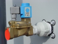
2) Valve/actuator compatibility (response matters)
The control package is only as good as the actuator. When I’ve seen recurring level oscillation, it’s frequently because the valve is too slow (or too fast) relative to the controller’s adjustment logic, or because the valve sizing doesn’t match makeup flow requirements.
Use these practical checks:
- Valve size and flow coefficient: Must match the expected makeup water demand.
- Stroke time / opening characteristics: Faster isn’t always better—what matters is matching system dynamics.
- Control signal type: Ensure the package and valve/controller input/output are compatible.
3) Electrical integration and safety
I always verify:
- Power supply requirements (voltage, frequency, and allowable tolerance)
- Control signal/wiring requirements for the rest of the tower controls (interlocks, enable/disable logic)
- Grounding and wire routing to reduce noise pickup from motors, VFDs, and pumps
If you’re retrofitting, pay special attention to how existing conduit routes can act like antennas. In a prior upgrade project, we reduced nuisance resets simply by rerouting sensor cable away from motor leads and improving shield termination practices.
4) Setpoint strategy and operating constraints
Your setpoint shouldn’t be a random number. It should reflect:
- Minimum basin level for stable pump operation and uniform distribution
- Maximum level tolerance to avoid overflow risk
- Blowdown and makeup schedule so chemical control and level control don’t fight each other
In stable operations, the level setpoint is treated as part of a system, not a standalone target.
Installation Checklist: What I Verify Before Power-On
Proper installation is where most “control problems” become obvious. Here’s my pre-energization checklist that aligns with how I’d approach a bac electric water level control package on a real jobsite.
Mechanical and sensor verification
- Confirm sensor location is appropriate for representative basin level (avoid direct spray zones and excessive turbulence).
- Check for obstructions and ensure the sensor can be cleaned or accessed during service.
- Verify basin is plumb and the mechanical design won’t cause persistent localized pooling near the sensor.
Hydraulic verification
- Confirm makeup water supply characteristics (pressure stability, presence of strainers, and any backflow prevention).
- Ensure the valve is correctly oriented (flow direction) and that piping isn’t trapping air.
- Verify any drain/bleed lines (if used) are installed to avoid dead volume effects.
Electrical verification
- Match controller power and input/output wiring to the package requirements.
- Check shielding/grounding practice for sensor cables.
- Confirm interlocks (e.g., tower operating mode enable) are connected so the controller acts only when the system is in the correct state.
First power-on discipline (my practical method)
Before I expect the system to “work,” I test it in a controlled sequence:
- Sensor signal sanity check: Confirm the controller reads reasonable level values.
- Actuator command check: Verify output commands the valve in the expected direction.
- Low-risk commissioning: Use test modes (if available) to avoid uncontrolled fill/overflow.
- Staged tuning: Adjust controller parameters gradually to prevent hunting.
This reduces the chance of the loop going unstable during the first hours of operation.
Tuning and Commissioning: Achieving Stable Level Without Hunting
Even with correct wiring and plumbing, a water level loop can oscillate if tuning doesn’t match site dynamics. In my experience, tuning success is less about “magic numbers” and more about respecting time constants.
Common symptoms and what they usually mean
| Symptom | Likely cause | What to check first |
|---|---|---|
| Level overshoots the setpoint repeatedly | Actuator too aggressive or controller gain too high | Valve response speed, control tuning parameters |
| Level hunts (goes up/down in a cycle) | Loop gain too high or sensor noise/turbulence | Sensor placement, cable shielding, filtering settings |
| Level drifts slowly over time | Valve sizing mismatch or control offsets | Flow capacity, setpoint recalibration, calibration drift |
| Controller seems unresponsive | Interlock disabled or output not commanding valve | Enable logic, output wiring, actuator feedback |
A tuning workflow I use
- Stabilize baselines: Let the system reach steady operation without chemical upset events or major demand swings.
- Adjust one variable at a time: If you change multiple tuning parameters simultaneously, you won’t know what fixed (or broke) the behavior.
- Use conservative incremental changes: Small adjustments reduce the risk of overshoot.
- Validate across conditions: Confirm performance during normal operation and during realistic makeup-demand changes (e.g., load transitions).
On one site, we improved basin level stability by treating tuning as a maintenance-friendly process: we documented the parameter set and the expected behavior band. That prevented the “it got worse after maintenance” cycle because technicians had a known reference point.
Maintenance and Reliability: Keeping the Control Loop Accurate
To keep a bac electric water level control package reliable, maintenance needs to focus on both the mechanical path (water flow and valves) and the measurement path (sensor accuracy).
What I recommend scheduling
- Sensor inspection and cleaning: Periodically remove scale/biofilm buildup that can bias level readings.
- Valve performance checks: Verify the valve moves freely and doesn’t stick due to sediment.
- Calibration verification: Confirm sensor readings against a trusted reference level method as part of routine service.
- Cable and connection audit: Look for loose terminals, moisture ingress, and damaged insulation in control cabinets.
Limitations you should plan for
Even a well-designed electric package can be limited by severe water quality, persistent sensor fouling, or inadequate makeup supply pressure. If you routinely operate with high solids or aggressive scaling conditions, you may need upstream filtration, water treatment adjustments, or a sensor location/design optimized for your basin environment.
FAQ
How do I confirm the bac electric water level control system is correctly calibrated?
Confirm calibration by comparing the controller’s indicated level to a trusted reference measurement method at multiple points (near minimum, setpoint, and near upper tolerance). If the readings consistently deviate, you’ll need sensor calibration/adjustment and verification of sensor mounting and fouling status.
Why does my basin water level oscillate even after installation?
Most oscillation comes from loop mismatch: valve response time relative to controller tuning, sensor noise from turbulence or wiring interference, or improper filtering/settings. Start by checking sensor placement and cable shielding, then review tuning parameters and valve sizing.
What maintenance items prevent long-term drift in electric level control?
Regular sensor cleaning, valve performance checks (including verifying free movement and no sediment sticking), periodic signal/cable inspection, and scheduled calibration verification are the most common drift-prevention steps I’ve used to keep level control stable over time.
Conclusion: A Practical Next Step
An electric water level control package succeeds when the entire control loop—sensor, controller, actuator, and site dynamics—works together. If you want stable operation, don’t just “install the kit.” Commission it with disciplined checks, tune it conservatively, and maintain the measurement and valve path so accuracy doesn’t degrade.
Next step: Write a one-page commissioning checklist for your site (sensor signal sanity check, actuator direction test, safe fill behavior, and a tuning step log). Use it during your first run and keep it for maintenance handoffs—this is the fastest way I’ve seen to turn a fragile loop into consistent basin level control.
Discussion