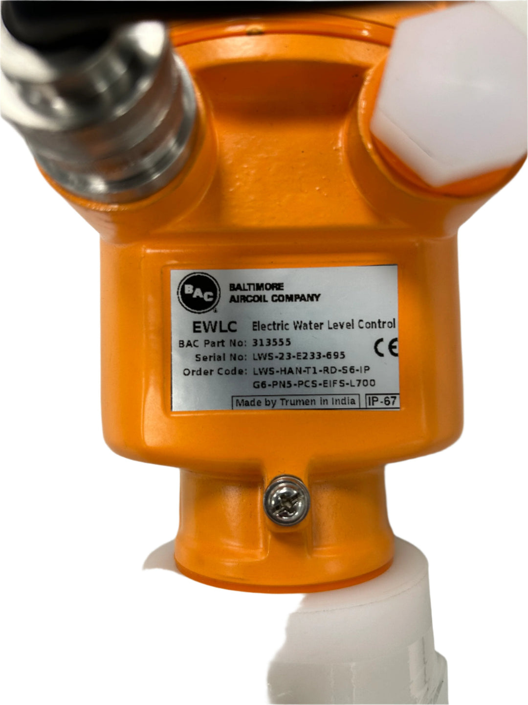
Bac Electric Water Level Control RK3644M5 - 313555
Why “bac electric water level control” keeps failing in the field
If you’ve ever walked into a plant or mechanical room and found water levels hunting up and down—or alarms firing without a clear cause—you already know the pain: water level control shouldn’t be a guessing game. In my hands-on work commissioning and troubleshooting hydronic and water systems, the most frustrating issues weren’t usually the pumps themselves; they were the control loop decisions behind the bac electric water level control strategy—sensor placement, signal stability, wiring quality, and control tuning.
This guide breaks down how bac electric water level control should be approached in real installations: what “good” looks like, the common failure modes I see, and a practical checklist you can use to diagnose issues quickly and reliably.
What bac electric water level control actually does (and why it’s different)
At its core, bac electric water level control is an electrical control approach that maintains a target water level by continuously reading a water level signal (often from an electrode/probe or level sensor), comparing it to a setpoint, and commanding output devices (such as a motorized valve, pump contactor logic, or a control relay) to correct deviations.
The control logic in plain terms
- Sensing: A level sensor converts water presence/height into an electrical signal.
- Decision: The controller compares the signal to the desired setpoint and applies control logic (often proportional or on/off with timing/hysteresis).
- Stabilization: Proper delays, filtering, and hysteresis prevent rapid cycling and “hunting.”
Why the “electric” part matters
In real systems, the electric side determines whether your control is stable or noisy. A sensor that’s electrically “fine” but mechanically installed incorrectly can create intermittent readings. A controller that’s correctly configured can still behave poorly if the input signal is noisy, the wiring is wrong, or the control parameters don’t match the dynamics of the tank and piping.
In my experience, the difference between a system that holds level for weeks and one that can’t settle comes down to signal integrity, correct input scaling, and control hysteresis/timing that matches actual fill and drain rates.
Hardware context: where RK3644M5 - 313555 fits into water control
The product reference “RK3644M5 - 313555” appears to be associated with an electrical control component used in water level management applications. Without assuming internal specifications you may have in your datasheet, the practical takeaway is this: any bac electric water level control device must be integrated with the correct sensor type, correct wiring topology, and correct control parameters for the system it’s controlling.
Integration matters more than the part number
When I evaluate installations, I don’t start with “Is the controller model correct?” I start with: “Is the sensor electrically compatible, is the signal grounded correctly, and does the controller’s switching/action map match what your system needs?” If any one of those is wrong, you’ll see unstable level control even if the controller itself is functional.
How to get stable levels: the field checklist I use
Below is the same structure I use during on-site troubleshooting when bac electric water level control is hunting, lagging, or triggering nuisance alarms. The goal is to isolate whether the problem is sensing, electrical signal quality, control settings, or system dynamics.
1) Verify sensor location and water contact conditions
- Check mounting height: Ensure the sensor reference point aligns with your desired “normal” level and low/high safety bands.
- Avoid splash zones: If the sensor is in a turbulence area, electrical readings can fluctuate rapidly.
- Confirm electrode cleanliness (if applicable): Scale, biofilm, and coatings can change conductivity and create unstable signals.
2) Check signal integrity (wiring and grounding)
- Use proper routing: Keep level sensor wiring away from high-voltage motor drives and contactor coils.
- Confirm shield/ground practice: If your setup uses shielded cable, terminate it as your manufacturer instructs.
- Inspect terminations: Loose or corroded terminals create intermittent readings that the controller interprets as real level changes.
- Match input type: Don’t connect a sensor type that outputs the wrong signal form; controllers can appear to “work” but never settle.
3) Align controller logic with your system dynamics
- Setpoint correctness: Confirm the setpoint corresponds to how the sensor reports level (some systems need calibration offsets).
- Use appropriate hysteresis/timers: If the controller switches too aggressively, the water level overshoots and hunts.
- Respect fill/drain rates: A tank with slow inflow needs different timing than one with fast inlet valves or variable-speed pumps.
4) Validate outputs and flow path behavior
- Confirm actuator response: Solenoid valves, VFD setpoints, and pump contactors must respond within expected time windows.
- Check for stuck valves or partial restrictions: If the system can’t actually change level quickly, control may keep “chasing” reality.
- Confirm return paths: Air locks or blocked drain lines can create a delayed response that looks like control failure.
A quick troubleshooting sequence that saves hours
- Observe the level trend for 10–20 minutes and note whether it’s noise (rapid jitter) or overshoot/lag (slow hunting).
- Check for wiring issues (especially shield/route/terminals) if you see rapid jitter.
- If you see overshoot/lag, adjust control hysteresis/timing and confirm actuator response speed.
- Only after electrical and control logic look correct, inspect hydraulic causes (valves, flow restrictions, air pockets).
Common failure modes I’ve seen with bac electric water level control
- Nuisance cycling: Often caused by insufficient hysteresis or a fill/drain mismatch.
- Intermittent level jumps: Usually wiring, loose terminals, corrosion, grounding issues, or sensor contamination.
- Slow recovery after setpoint changes: Usually actuator delay, valve stiction, restricted flow paths, or wrong timing parameters.
- Alarms without obvious level movement: Often the controller is reading a signal fault state (open circuit/incorrect input interpretation).
Pros and cons of typical electric water level control approaches
| Approach | What it’s good at | Where it can bite you |
|---|---|---|
| Probe/electrode sensing (when used) | Simple wiring, direct water contact logic | Scale/biofilm can shift signal stability |
| Level sensor with dedicated signal output | Better diagnostics and smoother signal (if installed correctly) | Signal wiring and grounding errors can still cause drift/jitter |
| On/off control with hysteresis/timers | Predictable switching and easier commissioning | Bad hysteresis/timing leads to hunting |
FAQ
What should I check first when bac electric water level control won’t hold level?
Start with sensing and wiring
In practice, I check sensor placement and cleanliness first, then verify signal integrity (routing away from noisy power wiring, correct shielding/grounding, and tight/corrosion-free terminations). If readings are noisy, the controller will correct “phantom level changes” and never settle.
Why does the water level hunt up and down with the controller installed?
Hysteresis/timing doesn’t match the system dynamics
Hunting commonly comes from aggressive switching (insufficient hysteresis) or actuator delays (valves/pumps respond slower than the control expects). Adjust hysteresis/timers and confirm the actuators actually change flow and level in the direction and timescale the controller assumes.
Can I reuse a water level controller if I change the sensor?
Only if the sensor signal type and input expectations match
Controllers vary in what they accept (signal form, voltage/current range, fail-state behavior). If the new sensor’s output type or scaling doesn’t match the controller’s input configuration, you can get unstable control or false alarms.
Conclusion: your next practical step
Stable bac electric water level control is rarely about “the controller alone.” In my hands-on commissioning work, the fastest path to success is: ensure sensor placement and cleanliness are correct, confirm signal wiring integrity, then align controller settings (setpoint, hysteresis/timing) with your tank’s real fill/drain behavior. Do that, and you’ll usually eliminate nuisance cycling and alarms.
Next step: Pick one problem symptom (rapid jitter vs overshoot/lag), record the water level trend for 10–20 minutes, and run the checklist in the order above—starting with sensor and wiring—before changing control parameters.
Discussion