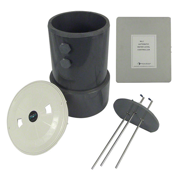
Bac Electric Water Level Control WLC1003PKG - Water Level Controller WLC-100-3 Package With Probes, Holder Plate, Connectors and Chamber
If you’ve ever had a pump run dry or a tank overfill because the water level signal was unreliable, you already know the real cost of bad control: wasted equipment, downtime, and frustrating troubleshooting. In my hands-on work commissioning water treatment and process systems, the biggest pain point is rarely “the controller itself”—it’s getting accurate detection, stable probe wiring, and repeatable switching under real-world conditions. This guide explains how bac electric water level control with probe-based switching works, what to verify during installation, and how to plan for safe operation over the long term.
What the WLC1003PKG package is designed to do
The WLC1003PKG (Water Level Controller WLC-100-3 Package with probes, holder plate, connectors, and chamber) is built around a common requirement in industrial and utility settings: detect a water level condition and switch a pump or related equipment with reliable repeatability. The “WLC-100-3” style configuration typically supports multiple level-related functions (e.g., low/high control logic) using a probe set designed for submersion sensing.
In practice, the controller + probe assembly is responsible for three things:
- Signal reliability: converting the probe’s wet/dry conductivity state into stable switching decisions.
- Control logic: mapping probe states to the pump (or alarm) action you intend.
- Operational safety: preventing unsafe states like dry running or uncontrolled overflow when conditions change.
Why probe-based electric water level control works (and where it can fail)
Probe-based electric water level control is effective because it uses a direct sensing method: the probe electrodes change their electrical characteristics when they are submerged (conductivity/wet condition) versus exposed (dry condition). That simple physical truth is what makes the system robust in many environments.
The underlying logic
At a high level, the controller monitors the probe states and uses them to drive outputs. In typical implementations, the controller determines one or more switching conditions such as:
- Low-level protection: stop the pump when water drops below the low probe.
- High-level control: stop or change state when the high probe indicates water has reached the desired level.
- Hysteresis / safe cycling: reduce rapid “on/off” cycling caused by wave action or small fluctuations (this depends on controller logic and configuration).
Where the real-world issues show up
In my installations, the failures weren’t caused by the concept—they were caused by mismatches between the probes and the environment. Common culprits include:
- Biofouling and scaling: buildup on probe surfaces can alter the conductivity path and create false detections.
- Wrong mounting depth or poor alignment: if probe positions don’t match the tank’s actual operating levels, the system will switch at the wrong time.
- Moisture intrusion in connectors: water ingress into terminal areas or connector backshells can introduce leakage paths.
- Noise and grounding problems: long cable runs near motors/VFDs can induce noise; poor cable routing or grounding can lead to unstable readings.
- Chemistry changes: conductivity varies with water quality. Very low-conductivity water may behave differently than expected.
Hands-on installation checklist for bac electric water level control
If you want the controller to behave consistently, the “installation details” matter as much as the electronics. Below is the checklist I use when we commission probe-based systems like WLC-100 controller packages.
1) Mounting and probe positioning
- Verify the chamber and holder plate geometry so the probe tips sit at the intended low/high setpoints.
- Account for sloshing and flow: in systems with turbulence, I recommend leaving margin so the controller doesn’t switch due to transient splashes.
- Confirm the probes are not resting against tank walls or obstructions that could wick water or create “partially wet” states.
2) Wiring quality and signal integrity
- Use proper cable routing away from high-power conductors when possible.
- Keep connector areas dry and sealed; if your connectors aren’t designed for wet mounting, shield them appropriately.
- If your site has motor drives, route probe wiring separately and ensure a consistent grounding approach.
3) Power and switching behavior
- Confirm the controller’s supply requirements match your site voltage and wiring configuration.
- Test the switching sequence in manual mode (if available) so you can observe output behavior before tying it to a production pump.
- Measure relay contact/solenoid load requirements—probe control doesn’t remove the need to confirm switching capacity and compatibility.
4) Commissioning tests (the part people skip)
My strongest advice: simulate conditions before you trust automation. Here’s what I typically validate:
- Dry test: verify the low condition is detected (pump should not start).
- Fill test: verify transitions at the intended levels (pump starts/stops as designed).
- Repeatability test: cycle the water level several times and confirm switching points are consistent and not drifting.
- Transient test: create brief disturbances (within safe limits) to ensure momentary splashes don’t trigger incorrect output states.
Operational best practices to keep electric level control stable
Even a well-installed bac electric water level control setup can drift over time if you ignore maintenance. Probe sensors are exposed to the same environment they measure.
Maintenance that actually helps
- Scheduled cleaning: remove scale or biofilm from probe surfaces at intervals based on water conditions.
- Inspect connectors: check for discoloration, corrosion, or looseness—especially after high-humidity seasons.
- Re-check level calibration: verify that setpoint positioning hasn’t been changed by tank modifications.
- Log symptoms: if you observe nuisance switching, note time, water conditions, and any pump cycling patterns. This speeds diagnosis.
Limits you should plan for
Probe-based electric level control is not universally perfect. It can be less suitable when:
- Water is extremely low conductivity: sensing may be less reliable unless the controller/probe design is intended for it.
- Media is highly conductive/dirty: buildup and leakage paths may increase false detections, requiring stronger maintenance discipline.
- You need ultra-precise continuous level measurement: probes like these are typically more suited to threshold control (low/high), not smooth analog level tracking.
FAQ
FAQ
Is bac electric water level control suitable for pump dry-run protection?
Yes—when the low-level probe is positioned correctly and the switching logic is configured to inhibit pump start under low-water conditions, probe-based controllers are commonly used for dry-run protection as a threshold control method.
Why do probe systems sometimes show false switching?
The most frequent causes are probe fouling (biofilm/scale), connector moisture ingress or leakage paths, poor probe mounting that creates partially-wet conditions, and electrical noise from nearby motor/VFD wiring. A structured commissioning test helps distinguish sensing issues from wiring/logic issues.
What’s the best next step before full automation?
Perform a controlled commissioning and repeatability test: cycle the water level through the intended low/high points multiple times, observe switching behavior, and confirm that transient splashing doesn’t trigger incorrect output states—then document the final probe positions and wiring routes for future maintenance.
Conclusion: make it reliable by focusing on setup and repeatability
In my experience, bac electric water level control succeeds or fails based on installation details: correct probe positioning, clean wiring practices, safe switching configuration, and repeatable commissioning tests. If you treat the WLC1003PKG as a system—not just a controller—you’ll avoid the most common reliability problems like nuisance trips, missed transitions, and dry-run risk.
Next practical step: plan a commissioning checklist for your exact tank—verify probe mounting against your real operating levels, run dry/fill/transient repeatability tests, and only then connect the controller to the pump for unattended operation.
Discussion